Blog
This article is being published as a historical reference. Written by J.E. Hubee, USA in May 1990
For the upgrading and renovation of an existing shiploading and unloading facility, primarily handling green and calcined petroleum coke, the ORBA Corporation of Houston, Texas, USA, was invited by AmClyde Engineering Products to prepare a detailed proposal for this project during the early spring of 1989.
The existing facility consisted of a traveling shiploader, a traveling hopper car and a reversible dock conveyor. This conveyor feeds the shiploader via a trailer, or by running the conveyor in a reversed direction it will receive the inbound material from the hopper car.
The hopper car could be loaded by the ship’s own unloading gear or by means of a mobile crane situated on the dock. As a result the dock became extremely congested and caused severe restrictions on the mobility of the shiploader as well as the hopper car.
GENERAL CONCEPTS
Obviously, the solution to this problem was to rid the dock of redundant equipment wherever possible, and it seemed that this could be achieved by using a single gantry with a dual function, loading as well as unloading. Although this concept was realized some years ago by AmClyde, previously known as the American Hoist & Derrick Company [1] for a floating transshipment facility, it was clear that a different design was required due to the inherent limitation of the existing dock.
The machine, as was visualized, should be able to load seagoing vessels up to 40,000 DWT and unload river barges. In order to realize such a concept technically and economically, it was then decided between the ORBA and AmClyde engineers that the following design parameters should be set and adhered to:
- Use an unloader gantry of common design to minimize additional engineering;
- Existing dock conveyor to be utilized;
- Weights of added bulk material handling components such as conveyors, chutes etc. To be kept to a minimum;
- Unloading function not to be restricted n any way by the additional shiploading machinery introduced;
- The added shiploading ability not to be affected by the unloading machinery;
- Horizontal length of the elevating conveyor system to be kept as short as possible in order to obtain maximum travel on dock.
The equipment was sized to unload green petroleum coke at a rate of 500 t/h and 800 t/h as loading rate for the calcined petroleum coke.
The maximum reach of the grab bucket was set at 98 ft measured from the center line of the gantry track to accommodate two river barges moored side by side. In order to load a 40,000 DWT vessel the loading spout or chute does not have to go beyond 93 ft from the center line of the track to reach the hatch opening. It was also decided that the required boom conveyor should be of a shuttle design with its loading spout platform running on the same track as the grab bucket trolley. This, of course, to provide for a balanced load distribution in the apron structure.
CONCEPTUAL DESIGN
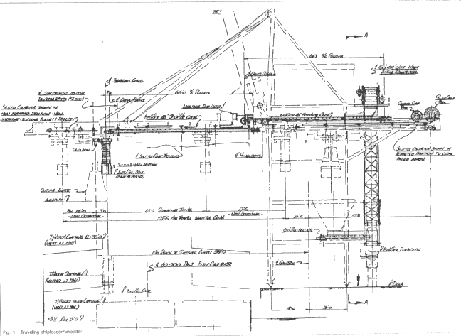
Adherence to the aforementioned parameters resulted in a conceptual design, as illustrated in the figure below. It consists basically of a standard type unloading gantry equipped with an elevating conveyor, fixed feed conveyor and a self propelled shuttle conveyor with telescopic chute at the discharge.
DESCRIPTION OF OPERATIONS
Shiploading
The outbound material is transported at a rate of 800 t/h to the conveyor system of the gantry by means of a new traveling tripper incorporated in the existing dock conveyor.
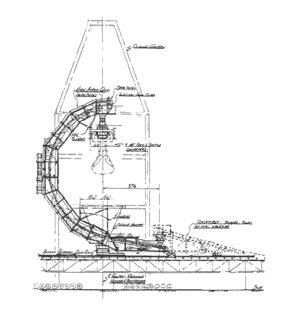
This tripper delivers the material onto the Sandwich Belt high angle convecyor [2] which in turn elevates the material in a semi-circular fashion onto the fixed feed conveyor situated on top of the gantry and fixed apron. From here the material is transported to the shuttle boom conveyor located within the hinged section of the apron, but above the clearance line of the grab bucket trolley.
The shuttle conveyor is suspended from a dual monorail by means of four multiple wheel trolleys at each side of the conveyor. The discharge pulley drive, head chute as well as the telescopic chute with its hoist and shuttle traverse machinery are accommodated on a separate traveling platform. This traveling platform, pin connected to the suspended conveyor deck, utilizes the same track as used for the grab bucket trolley.
During the shiploading mode the grab bucket trolley is fully retracted to location B2 and parked well within the gantry structure, while the bucket is lowered and resting on the grid of its receiving hopper.
Normal loading conditions for 40,000 DWT vessels require the shuttle conveyor and telescopic to travel between location marked C2 and C3 only.
Ship Unloading
When operations call for an unloading mode the shuttle conveyor has to be parked in its most forward location, whereby the telescopic is positioned as shown at C1.
This will allow free travel of the grab bucket trolley beneath the shuttle conveyor between locations marked B1 and B2.
The inbound material is fed onto the existing dock conveyor via the receiving hopper and belt feeder on the unloader.
CONCLUSIONS
During the conceptual design state of this project some interesting facts came into focus.
For instance, the existing design of the apron did not require major changes as the depth of girders and cross members remained the same. The floor of the machinery house, however, had to be raised to allow the passage of the fixed feed conveyor.
The use of an elevating conveyor as shown, eliminate a long trailing structure, thereby creating additional operating travel. Other benefits were, of course, in this case, the ability to unload without wasted dock length for the parking of the other gantry, the elimination of an additional power supply for the second machine.
Acknowledgements
The author wishes to thank Mr. J.A. Dos Santos of Continental Conveyor and Equipment Company as well as Messrs Walter J. Webber and Terry J. Thompson of AmCLyde for their information in preparation of this paper.
References
- Amhoist Brochure ME-031-1182; “Delta” Transloader Brochure 2MJR822, Marine Energy Division, The Capacity for Bulk Handling.
- Dos Santos, J.A. and McGaha, J.R.: Modern Continuous Haulage Systems; bulk solids handling, Vol. 9 (1989) No. 3, p. 307