Blog
Development of the sandwich belt high angle conveyor concept has come a long way since its first introduction in the early 1950s. Over the approximate thirty year period until 1979, significant advances were few and only came in spurts. Such advances did not build on previous developments. Rather, they were independent developments which soon reached their technical limitations. Sandwich belt high angle conveyor long term success followed the development by Joseph A. Dos Santos in the period 1979-1981.
Dos Santos Sandwich belt high angle conveyors are now well established in the industry with the first commercial unit beginning operation in 1984. Since then more than some 200 units have gone into operation throughout the world.
The first commercial Sandwich belt high angle conveyor for tunneling was also the very first vertical installation. The system was part of the Los Angeles metro expansion of the late 1980s. The excavation in this area was an open cut with timber lagging on steel beams to support the busy city street above while excavation proceeded below. Material movement was by load-and-carry with front end loaders to a grizzly covered hopper. The hopper loaded the tail of the high angle conveyor through a vibratory feeder. The high angle conveyor elevated the excavated earth continuously from under the street to a truck loading bin above. Though it was designed to load directly into the bin, for reasons of truck access and traffic flow, a connecting conveyor was added in order to locate the bin further away from the intersection of the two busy streets. The surge capacities of the hopper below and the bin above allowed independent discontinuous excavation and truck loading without interrupting the continuous elevating of the high angle conveyor. The system was designed to begin operation during the early excavation, requiring only 25 meters of lift. Then it was extended down as the depth increased, in 1.219 meter increments until reaching the design maximum depth and the corresponding design lift of 32.3 meters.
Valuable lessons learned during this early project included:
- Though the project was of short duration the duty was harsh.
- Oversized material consisting of large rocks and large clumps easily passed through the hopper’s grizzly which consisted of parallel 51mm wide bars spaced at 203mm.
- Such material was too large for the 914mm belt width and corresponding equipment.
- Though not detected by the layman, continuity of hugging lapse along the vertically straight elevating section prompted a review and revision of the continuity of hugging criteria.
Though the system completed its task successfully, it was decided that future Sandwich belt high angle conveyors for such projects would use wider belts (not less than 1200mm belt width), thicker damage resistant wear covers and rubber disc center rolls at idlers to soften the indents of the large lumps as they travel along the transition curves.
In 1993, the first Sandwich belt installation to elevate tunnel muck from a TBM (tunnel boring machine) was installed. This was part of the Chicago TARP (Tunnel and Reservoir Plan) project. The entire excavating and muck haulage system consisted of the TBM, a trailing conveyor below ground, the vertical Sandwich belt conveyor system to lift the material to the surface and finally a transfer and stacking system consisting of a grasshopper conveyor and radial stacker. As with subsequent systems the major equipment (drives and take-up systems) was located on the surface, at the head end so it could be easily accessed and serviced. Only the intermediate structure and tail pulleys were located underground. Additionally, the intermediate structure served as the support and guidance for the trailing conveyor’s return belt strands that were elevated to its belt storage unit located on the surface, 70 meters above.
This was the predecessor to the Paris units utilizing similar belt width and similar equipment though the material and operating conditions were not quite as harsh. Like the others it demonstrated successful vertical conveying.
SANDWICH BELT HIGH ANGLE CONVEYORS: THE CHOSEN SOLUTION AT PARIS METRO EXPANSION
From the first Sandwich belt application at a TBM in 1993, many years passed before the next installation. Although a few sandwich units were installed, pocket belt systems dominated the duties of elevating tunnel muck from the TBMs to the surface, even though the advantages of Sandwich belt high angle conveyors had been well demonstrated.
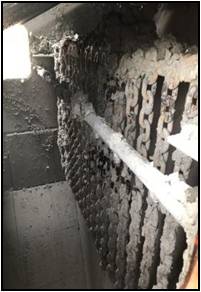
That advantage is the ability to handle and fully discharge very wet and sticky material because the smooth surfaced rubber belts can be continuously scraped clean. This advantage had long been demonstrated in the many Sandwich belt installations in other industries, particularly in municipal waste where many units elevated municipal sludge, sludge and sawdust mix, and some industrial sludges. Nearly all of these installations conveyed the sticky material vertically. By contrast, the tunneling industry had continued to struggle with handling tunnel muck at their pocket belt elevating systems. The pocket belt required at its discharge end a long overlap distance with the surface receiving conveyor and a series of eccentric rolls that beat the back of the pocket belt in order to dislodge caked material from the pockets and onto the outgoing conveyor below.
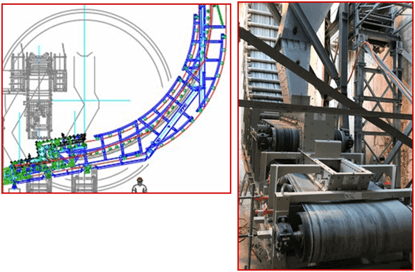
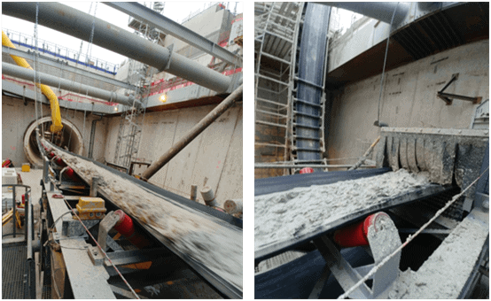
The Paris Metro expansion project finally acknowledged the distinct advantage of Sandwich belt high angle conveyors and specified them exclusively. Figures 3 and 4 provide a depiction and technical summary for each of the two Dos Santos International units supplied thus far at the Paris Metro expansion. These units share a common basic design but there are minor differences. For the common design rate of 800 t/h, the belt width is 1400mm and the belt speed is 3 m/s. This belt width is also compatible with the specified material size which it has handled very nicely.
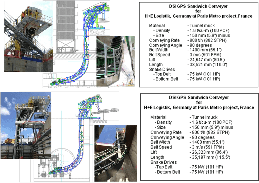
THE BELT LINE AND MATERIALS FLOW PATH
By following the carrying path from loading at the bottom to discharge at the top it can be seen that the bulk material loads onto the troughed bottom belt before it enters the sandwich. From the loading point, the bottom belt with the bulk material travels into the sandwich that is formed when it is joined by the top belt. At this point and beyond, the bottom belt, now in suspension, urges itself and the material up against the top belt which is supported by closely spaced inverted troughing idlers. The bottom belt and material is urged upward by a radial load which is due to the belt tension and the curved profile according to the equation P radial=Tension/Radius of the curve. This radial load must overcome the lineal weight of the bottom belt and conveyed material and must additionally provide the needed hugging pressure to develop the internal friction that will resist the gravitational slide back forces.
In this way, the bulk travels from the sandwich entrance through the lower transition curve to the start of the vertical profile. Along the straight vertical profile the needed hugging pressure is provided by the GPS sections. Each GPS section consists of two equalized idler-like assemblies of four equalized rolls so that all eight rolls are equalized. The equalized idler-like assemblies along the right side are positioned between the troughing idlers at the left and they urge the outer (right side) belt with material against the inner (left side) belt with a calculated pressure that is provided by a compression spring. Continuity of hugging without lapse is achieved by close spacing of the fully equalized idler rolls which have no preferred orientation and follow perfectly the arbitrary topography of the material surface at the outer (right side) belt. As with the radial load, the hugging pressure must be sufficient to develop the needed internal friction that will resist the gravitational slide back forces.
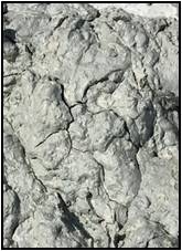
Beyond the straight profile, the belt sandwich with material travels through a short transition curve, a point of curvature reversal, then through another transition curve to discharge. Through the transition curves, as with the lower curve, the outer belt radially urges itself with the bulk material up against the inner curve which is supported by closely spaced troughing idlers. At the discharge point the bottom belt is deflected over its head/drive pulley and the material is released into the discharge chute. The top belt travels a little further to its head/drive pulley. Both belts return independently through their take-up paths then to their respective tail pulleys.
EQUIPMENT SUMMARY
In anticipation of the larger material, the belts are armored with 10mm thick carrying covers of Grade 1 rubber, the best resistant grade against wear, impact and cutting. Additionally, along the transition curves all CEMA D6 idlers have rubber disc center rolls and steel wing rolls. The rubber disc center rolls soften the ride of the larger lumps as they are urged radially by the outer belt against the inner belt. All pulleys are rubber lagged – plain at non-drive pulleys and diamond grooved for traction at the head drive pulleys. The non-drive pulleys are also crowned. The combination of lagging and crowning promotes good belt alignment. The lagging is also softer and more forgiving on those occasions when material enters the pinch between the belt and the pulley face.
Both belts are driven equally by shaft mounted drives at the head/discharge pulleys. Driving both belts shares the drive tension equally and facilitates better belt alignment than driving only one belt while the other merely follows. Variable frequency control at both drives facilitates equal load sharing, provides soft starts, and allows variation of the belt speed as may be deemed appropriate in response to the actual material and flow characteristics. Tension control is by near-constant pressure hydraulics. A tensioning cylinder at each belt pulls on the take-up pulley carriage and operates within a narrow band of hydraulic pressure, pumping at the lower operating limit and stopping at the higher operating limit.
ARRANGEMENT AND STRUCTURE
The common design of the two conveyors in Paris is for the current requirements and for the long term. Because tunneling and construction projects tend to be of short duration, lasting several years at most and typically less than two years, it is difficult to justify the cost of custom, dedicated equipment. It was thus important that we provide a common design that would address the current requirements and the requirements of future projects. Accordingly, DSI designed the system to easily decrease or increase the vertical lift, to a possible low of 19.6 meters and a possible high of 43 meters. This can be done by subtracting or adding vertical structure (and belt length) in lengths that are multiples of 1676mm, the length coverage of each GPS (Gently Pressed Sandwich) hugging pressure module.
Thus the system and equipment must be designed for the maximum lift. To facilitate the extension and contraction, the system is modular with most equipment on the surface for easy access and service. The intermediate structure is of simple parallel channel sections and hangs down, suspended from the head end. At the bottom, the loading station and approach structure is supported at the loading end (left side) on grade and at the vertical (right side) by the hanging intermediate structure. Strategic bolted splice points along the vertical facilitate the adding and subtracting of vertical structure as required for each subsequent installation. With this arrangement and structure the lower loading section and vertical intermediate sections are kept simple with most vital equipment located at the head end.
THE DIFFERENCES
Though having the same common design the units differ slightly in adaptation to their respective requirements. One unit required less vertical lift by 1676mm, the length of one GPS section.
The other unit had a different requirement related to the TBM’s initial development. During the initial excavation, a temporary trailing conveyor was used. It was aligned along the tunnel’s center so that the discharge from this conveyor was located over the return of the top belt. For this a loading table with impact idlers and loading skirts was designed for the return of the top belt. Thus the muck could be conveyed back to the loading area of the bottom belt. Once on the bottom belt, the muck reverses direction and travels into the
belt sandwich then on to the discharge at the top. The sketch shows loading of the top return belt during the initial tunnel development. It is especially convenient that with VFD control of the drives during this early development the Dos Santos Sandwich belt conveyor could be run at a reduced speed mitigating the effects of the sudden reversal of the material flow. This feature was only used at one of the units, but it is available at either unit when needed in a future installation.
EARLY OPERATION, ADJUSTMENTS
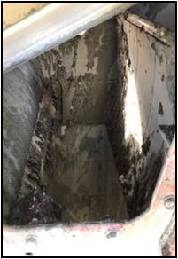
The Paris Metro Expansion is well vindicated in their exclusive specification of the Sandwich belt high angle conveyors for the muck elevating duties. Because of earlier units, it was known the muck would be sticky but no one anticipated how wet and sticky.
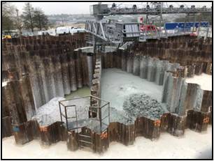
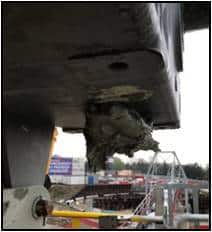

Project specifications did not provide sufficient guidelines to cope with the material found. No one was prepared, including those who supplied conventional conveyors for the project. The muck could best be described as goop or very wet goop. When stacked at the surface containments the muck becomes submerged under the water that was conveyed with it. Muck thrown at the underside of the top belt drive base stayed there.
Flow through the chutework dragged or plugged. Ironically, more water was sprayed on the material to keep it moving. Chute covers were removed to allow water spray with hoses. The original supply included a profiled deflector plate as is common to guide the discharge. This too became an obstacle and was replaced with a hanging chain curtain. The flailing motion of the latter made it self-cleaning.
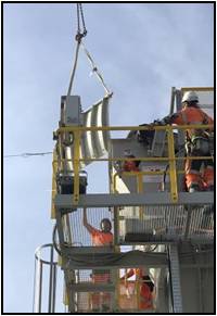

Though elevating the muck was never the problem, scraping the belts clean proved challenging. Field adjustments, including by the scraper manufacturer’s representative did not sufficiently improve their performance. Ultimately these were replaced with better scrapers that did clean the belts. The successful scrapers have individually sprung blades with positive attack angle. They have sufficient range of motion to follow the belt’s dirty surface. This is especially important at the top belt as its surface is deflected upward at the middle by the material load.
The changes and adjustments mentioned greatly improved the Sandwich belt operation and it continues operating without interruption. Production and material flow problems continued at the TBM, especially at the inclined section of the discharge conveyor where globs of wet clay tended to slide and stagnate. Along with the customer, DSI observed that the design capacity of the vertical Sandwich belt units was not being challenged. They thus took advantage of the VFD speed control and reduced the operating speed from 3 m/s to 2.4 m/s (from 50 Hz to 40 Hz). This proved to handle the production very well while reducing the wear and tear associated with belt speed.
SUMMARY AND CONCLUSION
Despite the long tradition of pocket belts for vertical muck haulage from TBMs, the distinct advantage of Sandwich belt high angle conveyors was recognized and they were specified exclusively at The Paris Metro Expansion. This writing documented the success in the face of a most adverse material. There have been other projects that have followed suit and have specified Sandwich belt high angle conveyors for the elevating duties when the material is especially sticky. With the remaining work at the Paris Metro Expansion and the others that have followed suit, the opportunity now presents itself for a quantum leap in Sandwich belt high angle conveyors at construction and tunneling projects, especially for the high volumes produced by the largest TBMs.